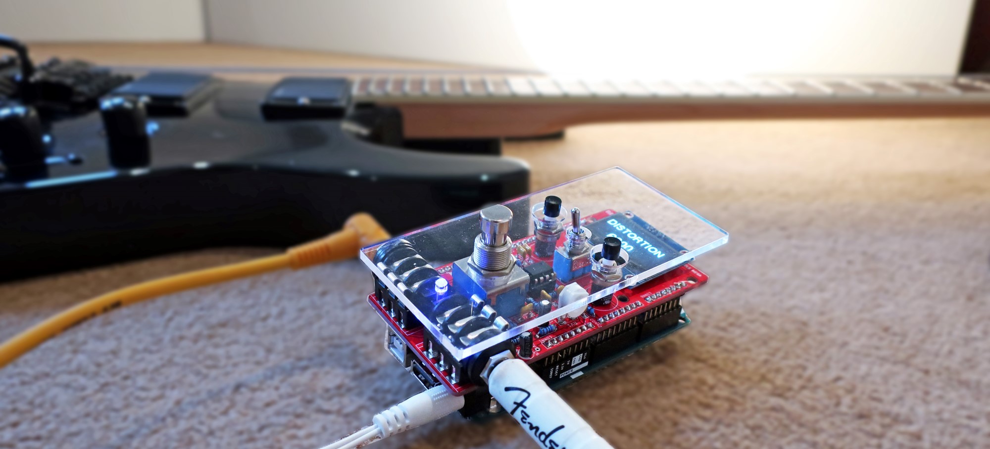
pedalSHIELD MEGA is a programmable guitar pedal that works with the Arduino MEGA 2560 and MEGA ADK boards. It includes a 1.3 inches OLED screen, a True Bypass footswitch, 2 programmable push-buttons and an analog input/output stage. The project is Open Source & Open Hardware and aimed for hackers, musicians and programmers that want to learn about DSP (digital signal processing), guitar effects, and experiment without deep knowledge on electronics or hardcore programming.
You can program your own effects in C/C++ with the standard Arduino IDE tool and get inspired using the library of effects posted on the pedalSHIELD MEGA online forum.

Circuit Explanation:
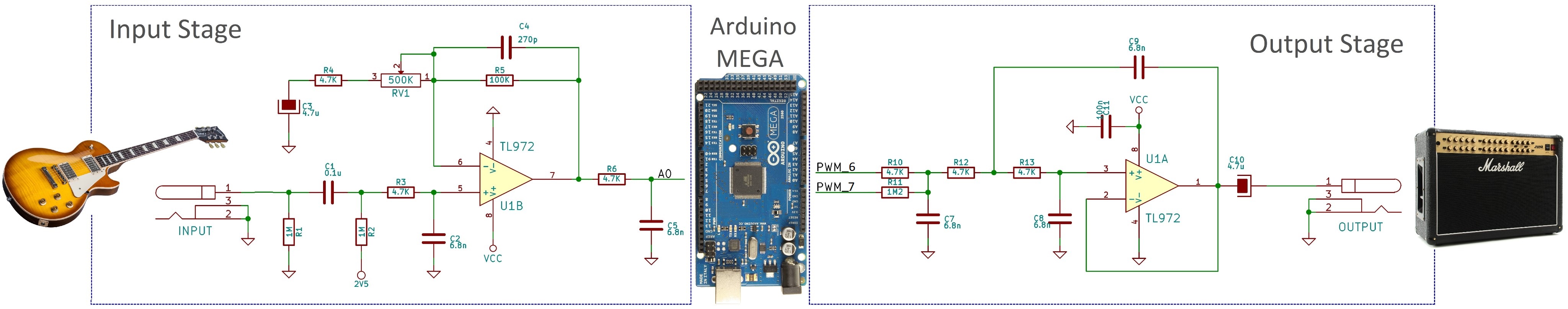
This shield that is placed on top of an Arduino MEGA has three parts:
- Analog Input Stage: The weak guitar signal is amplified and filtered, making it ready for the Arduino MEGA ADC (Analog to Digital Converter).
- Arduino MEGA Board: It takes the digitalized waveform from the ADC and does all the DSP (Digital Signal Processing) creating effects (distortion, fuzz, volume, delay, etc).
- The Output Stage: Once the new effected waveform is created inside the Arduino MEGA board, this last stage takes it and using two combined PWMs generates the analog output signal.
If you want to understand all the details of the circuit, please read the pedalSHIELD MEGA Circuit Analysis.
Specifications.
- Based on Arduino MEGA 2560 / ADK (16MHz, 8KB RAM).
- Analog stages using TL972 rail-to-rail operational amplifier.
- ADC: 10bits.
- Output Stage: 16 bits (2x8bits PWMs running in parallel)
- OLED Screen: 128x64 resolution, 1.3 inches (also compatible with 0.96"), I2C.
- Interface:
- 2 Configurable push buttons.
- 1 Configurable switch.
- 1 programmable blue led.
- True Bypass Foot-switch
- OLED Display.
- Connectors:
- Input Jack, 1/4 inch unbalanced, Zin=0.5MΩ.
- Output Jack, 1/4 inch unbalanced, Zout=0.1Ω.
- Power supply: power taken from the Arduino MEGA board (12V DC).
pedalSHIELD MEGA Review by BlitzCityDIY
You can check BliyzCityDIY deep review on Youtube:
How to Program it:
To make the programming as easy as possible, the standard Arduino IDE is used. All the effects are programmed on C/C++ (mainly C) using the standard Arduino functions. All tools and programs are free-of-charge/Open Source. The OLED screen uses the U8glib libraries (in the forum there is a tutorial explaining how to install the Ug8lib and use them with some examples.)
Basic knowledge of C is needed to understand the codes. The best way to illustrate how to program it is showing a simple example:
Clean Volume/Booster Pedal:
The block diagram of the software looks like this:
 The real code used looks like this:
#include "U8glib.h"
U8GLIB_SH1106_128X64 u8g(U8G_I2C_OPT_NO_ACK);  // Display which does not send ACK

//defining hardware resources.
#define LED 13
#define FOOTSWITCH 12
#define TOGGLE 2
#define PUSHBUTTON_1 A5
#define PUSHBUTTON_2 A4

//defining the output PWM parameters
#define PWM_FREQ 0x00FF // pwm frequency - 31.3KHz
#define PWM_MODE 0 // Fast (1) or Phase Correct (0)
#define PWM_QTY 2 // 2 PWMs in parallel

//other variables
int input, vol_variable=10000;
int counter=0;
unsigned int ADC_low, ADC_high;

void setup() {

      u8g.firstPage();
 do {
    u8g.setFont(u8g_font_helvR18r);
    u8g.drawStr( 0, 30, "BOOSTER");
    u8g.drawStr( 0, 60, "  EFFECT");
    } while( u8g.nextPage() );

  //setup IO
  pinMode(FOOTSWITCH, INPUT_PULLUP);
  pinMode(TOGGLE, INPUT_PULLUP);
  pinMode(PUSHBUTTON_1, INPUT_PULLUP);
  pinMode(PUSHBUTTON_2, INPUT_PULLUP);
  pinMode(LED, OUTPUT);
  pinMode(6, OUTPUT); //PWM0 as output
  pinMode(7, OUTPUT); //PWM1 as output

  // setup ADC
  ADMUX = 0x60; // left adjust, adc0, internal vcc
  ADCSRA = 0xe5; // turn on adc, ck/32, auto trigger
  ADCSRB = 0x00; // free running mode
  DIDR0 = 0x01; // turn off digital inputs for adc0

  // setup PWM
  TCCR4A = (((PWM_QTY - 1) << 5) | 0x80 | (PWM_MODE << 1)); //
  TCCR4B = ((PWM_MODE << 3) | 0x11); // ck/1
  TIMSK4 = 0x20; // interrupt on capture interrupt
  ICR4H = (PWM_FREQ >> 8);
  ICR4L = (PWM_FREQ & 0xff);
  DDRB |= ((PWM_QTY << 1) | 0x02); // turn on outputs
  sei(); // turn on interrupts - not really necessary with arduino
  }

void loop()
{
  /*This effect does not have oled screen updates, when using the "map" function the
  code goes too slow to be used the oled in real time.*/

    //Turn on the LED if the effect is ON.
  if (digitalRead(FOOTSWITCH)) digitalWrite(LED, HIGH);
     else  digitalWrite(LED, LOW);
}

ISR(TIMER4_CAPT_vect)
{
  // get ADC data
  ADC_low = ADCL; // you need to fetch the low byte first
  ADC_high = ADCH;
  //construct the input sumple summing the ADC low and high byte.
  input = ((ADC_high << 8) | ADC_low) + 0x8000; // make a signed 16b value

//// All the Digital Signal Processing happens here: ////

counter++; //to save resources, the pushbuttons are checked every 100 times.
if(counter==100)
{
counter=0;
if (!digitalRead(PUSHBUTTON_2)) {
  if (vol_variable<32768)vol_variable=vol_variable+20; //increase the vol
    digitalWrite(LED, LOW); //blinks the led
    }

    if (!digitalRead(PUSHBUTTON_1)) {
  if (vol_variable>0)vol_variable=vol_variable-20; //decrease vol
  digitalWrite(LED, LOW); //blinks the led
    }
}

  //the amplitude of the input signal is modified following the vol_variable value
  input = map(input, -32768, +32768,-vol_variable, vol_variable);

  //write the PWM signal
  OCR4AL = ((input + 0x8000) >> 8); // convert to unsigned, send out high byte
  OCR4BL = input; // send out low byte
}
pedalSHIELD MEGA Hardware Design.
As an Open Source project, the design was done using KiCad (free/open ECAD tool). All the project files, schematics, and Bill of Materials are public. The circuit can be broken down into 6 simpler blocks: Power Supply, Input Stage, Output Stage, User Interface, OLED Screen and Arduino Connectors:
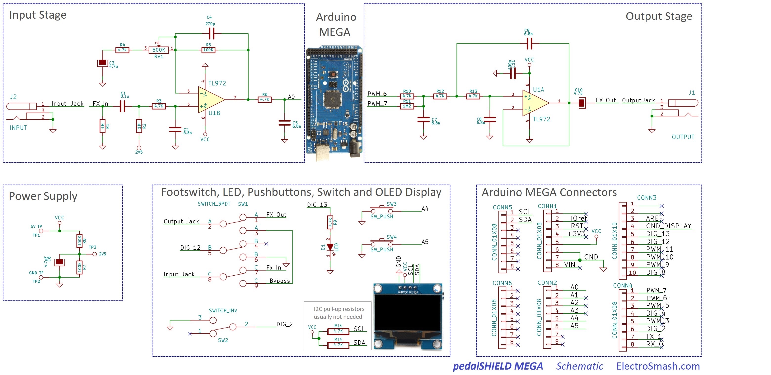
The main functionality is simple; 1 op-amp will prepare the signal to be digitized (Input Stage) and also 1 op-amp will recover the signal from the Arduino MEGA microcontroller (Output Stage). One 10bit ADCs is used to read the guitar signal and two PWM signals (16bits) are used to generate the output signal.
- Input Stage: The weak guitar signal is amplified for better acquisition using 1 op-amp (this part of the circuit is very similar to the MicroAmp guitar pedal design, check it for more details). The trimmer VR1 adjusts the gain of this amplifier from 1 to 21, so the guitar level can be optimized and any guitar will work. The signal pass through 3 low pass filters (formed by R3&C2, R5&C4, R6&C5) that will remove the excess of high harmonics that can create aliasing during the ADC signal acquisition (fc=5KHz).
- Output State: Uses a Sallen & Key 3rd order low pass filter which removes harmonics above 5KHz (Anti-aliasing filter). Two PWM 8-bit signals are used in parallel improving the bit resolution (2x8bits=16bits). If you want to read more about the PWM audio generation read the forum topic dedicated to the PWM configuration options. There is a fantastic research done by OpenMusic Labs referring to this topic.
- Power Supply: The pedal uses the +5V from Arduino MEGA to feed the rail-to-rail operational amplifier and achieve design simplicity and maximum signal swing without clipping. A resistor divider R7&R8 generates 2.5V for virtual ground and the cap C6 remove ripple on the power line.
- User Interface: The player can use 2 configurable push-buttons, 1 configurable toggle switch, 3PDT true-bypass footswitch, and a programmable LED.
- Oled Screen: A 1.3 inches Oled display is used to show values, images and details of the effect played. It uses I2C bus to communicate with the Arduino MEGA controller. 2 Pull-up resistors are placed in the case that the display needs it, but by default, they are not needed.
- Arduino MEGA Connectors: pin headers will link the shield with Arduino MEGA transferring the signals and power supply.
There are 2 options in the online shop:
- Order only the PCB. It uses easy-to-find standard components and you can build the kit yourself. The bill of materials is public with all the references and the Mouser part numbers.
- Order the Full Kit: This kit includes the PCB, Cover and all the components to build pedalSHIELD at home.
All the transactions are done through PayPal for maximum security.
If you have any question, contact us.
pedalSHIELD MEGA Bill Materials / Part List:
The components are easy-to-find through-hole parts with the minimum number of references:
| pedalSHIELD MEGA Bill of Materials. | ||||
| Reference | Qty | Value | Description | Mouser Reference |
| Capacitors | ||||
| C5,C2, C7, C8, C9 | 5 | 6.8n | ceramic cap | SR211C682MARTR1 |
| C3, C6, C10 | 3 | 4.7u | electrolytic cap | ECE-A1EKA4R7 |
| C1, C11 | 2 | 100n | ceramic cap | SR211C104KARTR1 |
| C4 | 1 | 270p | ceramic cap | D271K20Y5PH63L6R |
| Resistors | ||||
| R12,R13, R10, R9, R6, R4, R3 | 7 | 4.7K | Resistor, 1%,1/4W | MFR-25FRF52-4K7 |
| R5, R7, R8, | 3 | 100K | Resistor, 1%,1/4W | MFR-25FRF52-100K |
| R1, R2 | 2 | 1M | Resistor, 1%,1/4W | MFR-25FRF52-1M |
| R11 | 1 | 1M2 | Resistor, 1%,1/4W | MFR-25FRF52-1M2 |
| Others | ||||
| RV1 | 1 | 500K | resistor trimmer | 3319W-1-504 |
| D1 | 1 | Led 3mm blue | blue led 3mm | SSL-LX3044USBC |
| U1 | 1 | TL972 pdip-8 | op-amp rail-to-rail | TL972IPE4 |
| socket | 1 | dip 8 socket | socket dip8 | 1-2199298-2 |
| SW1 | 1 | 3DPT foot-switch | 3PDT foot-switch | 107-SF17020F-32-21RL |
| SW2 | 1 | Toggle switch | SPDT toggle switch | 612-100-A1111 |
| SW3, SW4 | 2 | Push-button | off-on push-button | 103-1013-EVX |
| Conn1,2,3,4,5,6,7 | 2 | 40 pin header | 2.54 pitch pin header | 710-61304011121 |
| J1, J2 | 2 | 1/4 Jack audio | stereo 6.35mm jack | NMJ6HCD2 |
| OLED Display | 1 | 1.3 inches, 4 pins | I2C OLED Display 1.3” | |
Frequently Asked Questions (FAQ):
What is Arduino Mega?
- Arduino MEGA is a single-board microcontroller to make using electronics in multidisciplinary projects more accessible. The hardware and software are open-source.
Where can I buy Arduino MEGA board?
- All major suppliers like Mouser, element-14, Digikey, RS-Online have it in their catalog and also you can find it on eBay, Amazon and physical electronic shops like Maplin or Radioshark.
Is pedalSHIELD MEGA compatible with all Arduino boards?
- No, only with Arduino MEGA 2560 and MEGA ADK. We also have other shields that work with other Arduino boards: pedalSHIELD UNO, pedalSHIELD DUE, Pedal-Pi.
Is pedalSHIELD MEGA suitable for bass players?
- Yes, but you need to swap 1 capacitor (C1) from 0.1uF to 0.47uF, allowing lower frequencies into the circuit, that is all.
Can I plug headphones directly into pedalSHIELD MEGA?
- No, pedalSHIELD MEGA is not an amplifier. It needs to be plugged into a guitar amplifier or to a multi-effects (Line 6 pods, etc..).
Thanks for reading, all feedback is appreciated 
Some Rights Reserved, you are free to copy, share, remix and use all material.
Trademarks, brand names and logos are the property of their respective owners.


